
High Output Corrugated Pipe Machine Delivers Unmatched Production Speed
2026-11-02
Speed claims are easy to make, but on a busy factory floor, they rarely survive contact with real-world demands. That’s what makes the latest corrugated pipe machine from COMRISE worth a closer look: it pairs genuinely high output with the kind of stability that keeps operators from hovering over the control panel. In this post, we’ll break down what those production numbers actually mean and why they matter for your bottom line.
Speed Metrics That Actually Hold Up on the Factory Floor
Most plants still lean on pieces per hour or units per shift as their go-to speed metrics. The problem is those numbers fall apart the moment a line starts and stops, or when a batch gets reworked at the end. A machine can hit its hourly target all day while the downstream station drowns in defects, so the headline number looks fine but the floor is actually crawling. If you want a speed metric that survives contact with reality, you have to measure what happens between the first good piece and the last good piece, not just what the counter says at the exit.
One metric that actually holds up is takt attainment measured at the bottleneck, not averaged across the line. Averaging hides the fact that one station is running at 110% while another limps at 70%, and the limping station is what sets your true pace. Another solid one is the median changeover time over a rolling two weeks, because changeovers are where speed gets quietly killed. Mean changeover time gets skewed by one disastrous setup, but the median tells you what a typical switch actually costs you. Both of these force you to look at the constraint and the interruptions, not just the final tally.
You can also track first-pass throughput per labor hour to keep the speed honest. If you only count units that make it through without rework on the first pass, the metric can't be gamed by running scrap faster. Pair that with a short interval control chart of cycle time spread—actual cycle times sampled every hour from the bottleneck—and you start seeing speed problems before they become end-of-shift surprises. These aren't fancy dashboard numbers; they're the ones that survive a walk through the floor with a stopwatch and a clipboard.
The Feeding and Melting Setup Behind Continuous High Output
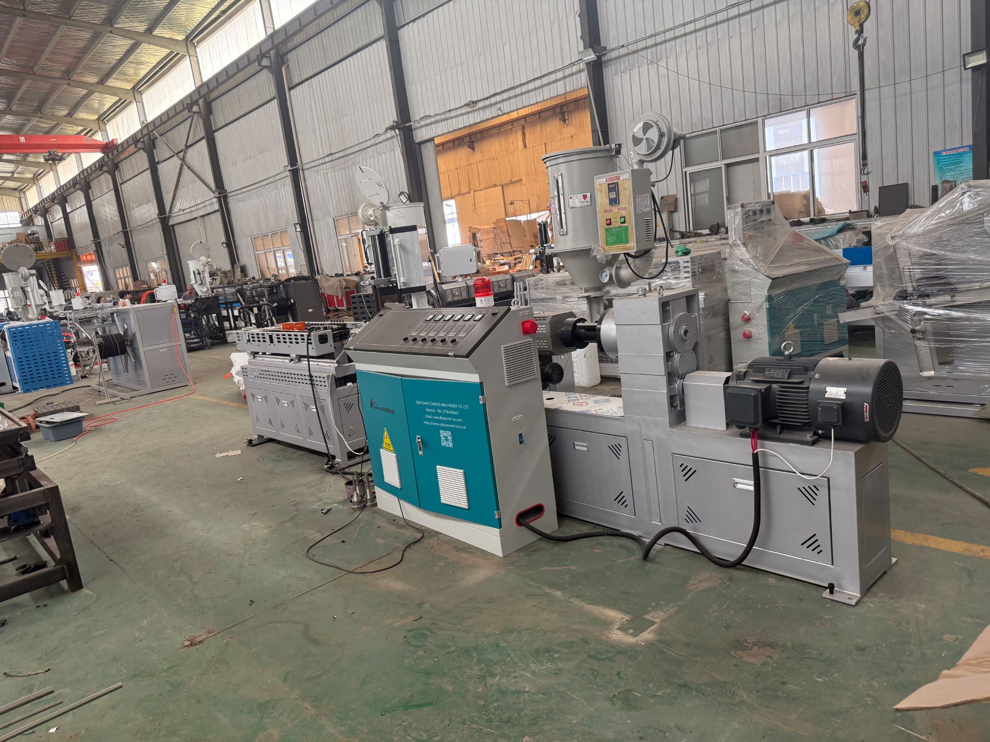
Continuous high output doesn't come from pushing a single component harder, but from tuning the entire feeding and melting chain so nothing fights against the process. The setup begins with a gravimetric feeder that meters material by weight rather than volume, compensating automatically for bulk density shifts. The barrel temperature profile is split into zones that can be finely adjusted, keeping the melt temperature within a narrow band as screw speed changes. This prevents the surging and pressure drops that quietly rob throughput when no one is watching the trend line.
The screw geometry itself plays an outsized role. A design with a deeper feed section and a progressively shallower compression zone ensures the polymer is conveyed without starving, then melts uniformly under controlled shear. Barrier flights separate the solid bed from the melt pool, forcing heat into the remaining solids while avoiding unmelted particles reaching the die. Combined with a melt pump between the screw tip and the die, the system delivers a consistent volumetric flow regardless of minor viscosity swings, which is exactly what allows the line to run for days without manual tweaks.
In practice, the whole arrangement is instrumented with melt pressure and temperature sensors feeding back to the controller. Rather than relying on preset recipes, the control logic adjusts screw speed and heater duty to hold a target melt pressure at the die. This closed-loop approach removes the guesswork from high-output operation. It also lets operators push the rate confidently, knowing the feeding and melting stages won't fall out of sync and create voids, degradation, or dimensional drift in the final product.
Why This Machine Rarely Needs to Pause for Adjustments
Most machines in this class need frequent fine-tuning because their alignment drifts as temperatures change or tooling wears. This one doesn't. The core reason is a closed-loop feedback system that watches key dimensions on every cycle and makes micro-corrections before they become visible defects. You rarely touch the dials because the machine is already compensating in real time.
Another factor is the rigid frame and thermally stable materials. Many operators spend half their shift chasing backlash or thermal expansion. Here, the base casting and linear guides are matched so closely that adjustments stay locked for months. Even after a cold start or a long run, the zero points hold steady enough that you can trust the first part as much as the hundredth.
Changeovers used to mean calling a technician. This machine uses self-locating fixtures and tool presetters that read offsets automatically, so switching from one product to the next is more about loading a program than turning wrenches. That's why production planning doesn't have to budget time for tweaking—the machine handles the variables that normally slow things down.
Maintaining Pipe Quality When Line Speed Climbs
Faster line speeds put more stress on the extruder and downstream equipment, and that's where quality can start to slip. The most common failure is eccentric wall thickness because the melt doesn't have enough time to stabilize inside the die. You might also see surface roughness or internal stresses that only show up after cutting. Instead of just cranking up the haul-off, operators need to watch melt pressure and barrel temperatures more closely, since small fluctuations get amplified when throughput rises.
One approach that works is to adjust the die gap and vacuum calibration setup rather than relying on screw speed alone. A larger die gap at higher line speeds lets the polymer relax before sizing, which reduces orientation and keeps roundness in check. Running the vacuum tank a bit hotter at the first section also helps the pipe skin form without dragging. Real-time diameter and wall monitors become essential, because by the time a problem shows up in a batch test, you've already produced several hundred feet of scrap.
Changeover Design That Keeps Production Windows Short
Short production windows don't come from working faster during the changeover itself—they come from stripping out anything that forces the line to stop for avoidable reasons. A well-designed changeover treats every bolt, hose, and setting as a candidate for elimination or conversion. Instead of unscrewing four clamps, a single cam-lock releases the entire guard. Instead of reaching for a toolbox, operators find the exact tool already mounted at the point of use. Small details like these quietly remove minutes that most teams have learned to accept as normal.
Pre-staging is often the difference between a ten-minute swap and a forty-minute one. Anything that can be prepared while the current job is still running—new dies on a preheated cart, ingredients weighed and staged, software recipes verified—belongs outside the critical path. The changeover design should force this discipline by giving every upcoming job a designated kit location near the machine, not in a distant crib. When the last good part comes off, the next setup should already be within arm's reach.
The final layer is mistake-proofing. A changeover that is fast but prone to wrong alignment, missed connections, or incorrect parameter entry will eventually eat its savings in rework. Use physical keys, asymmetric mounts, and quick-connect fittings that can only go together one way. Color-code the few remaining manual adjustments and put a simple visual check sheet on the control panel. That way, the operator spends the short window confirming readiness instead of hunting for errors.
How the Cooling Stage Keeps Up With Faster Extrusion
Pushing extrusion lines to higher throughputs quickly shifts the bottleneck downstream to the cooling tank. A traditional water bath that worked fine at 50 meters per minute often fails at 80 or 100, leaving the profile soft, sagging, or dimensionally unstable. Simply adding more length isn't always practical, so the cooling stage has to become smarter rather than just bigger.
One effective approach is to break the cooling into zones with independent temperature control. The first zone uses warmer water to prevent thermal shock and surface defects, while later zones run colder to strip heat rapidly. Turbulent flow matters more than raw water volume—directing high-velocity jets at the profile's thick sections pulls heat away far faster than a calm bath. Vacuum sizing combined with spray cooling also helps, as it keeps the extrudate tight against the calibrator walls while water droplets continuously remove heat from the surface.
Ultimately, keeping up with faster extrusion means treating cooling as an active process, not a passive soak. Sensors that monitor water temperature and flow allow real-time adjustments, while modular tank designs let processors reconfigure cooling length and spray patterns for different profiles. With the right setup, the cooling stage can handle higher line speeds without sacrificing dimensional accuracy or surface finish, making it a true partner to the extruder rather than a trailing constraint.
FAQ
It can consistently hit output rates that most conventional lines simply can't match, thanks to a reinforced drive system and an optimized cooling path that keeps the pipe moving without bottlenecks.
Operators often report exceeding their shift quotas by a noticeable margin because the machine maintains a steady pace with fewer slowdowns for adjustments or minor jams.
Yes, the quick-change forming modules let you switch between common diameter ranges in under an hour, so you aren't locked into a single product size.
It handles both virgin HDPE and recycled polypropylene blends without sacrificing wall consistency, which helps keep material costs under control.
Not really. The vacuum calibration tank holds dimensions tightly even at top speed, and the inline perforation unit stays accurate because it's synchronized with the haul-off speed.
Daily checks on the gearbox oil level, die head temperature sensors, and saw blade sharpness are usually enough; the self-lubricating chain tracks reduce the usual weekly greasing workload.
In most cases, yes. The control cabinet supports common fieldbus protocols, so you can tie it into your current PLC setup without ripping out the whole line.
It's about 15% shorter than previous generations because the cooling section uses a stacked water channel design, which frees up floor space for material staging or downstream equipment.
Conclusion
On a busy factory floor, claimed production speeds often fall apart under real operating conditions. This corrugated pipe machine backs its numbers with components built for sustained throughput. The feeding and melting section uses a high-torque, deep-flight screw paired with a barrel sized to keep the polymer moving without shear overheating. Because melt temperature and pressure remain stable, operators rarely stop the line for manual tweaks. Most adjustments happen through the control panel, and the machine holds its setpoints shift after shift.
As line speed climbs, pipe wall consistency and corrugation depth can suffer, but this design counters that with a vacuum calibration sleeve and an air-cooled forming block that lock dimensions in place before the pipe cools. Changeovers between diameters or profiles take under thirty minutes thanks to quick-release clamps and a rail system that slides the corrugator out of the way. Meanwhile, the cooling stage uses a multi-zone water spray and a chiller sized for the machine's maximum extrusion rate, so the pipe exits at a handling temperature without warping. The result is a production window that stays short, waste stays low, and output stays high.
Contact Us
Contact Person: LISA LEE
Email: [email protected]
Tel/WhatsApp: +86 13780696467
Website: https://www.qdpipemachine.com