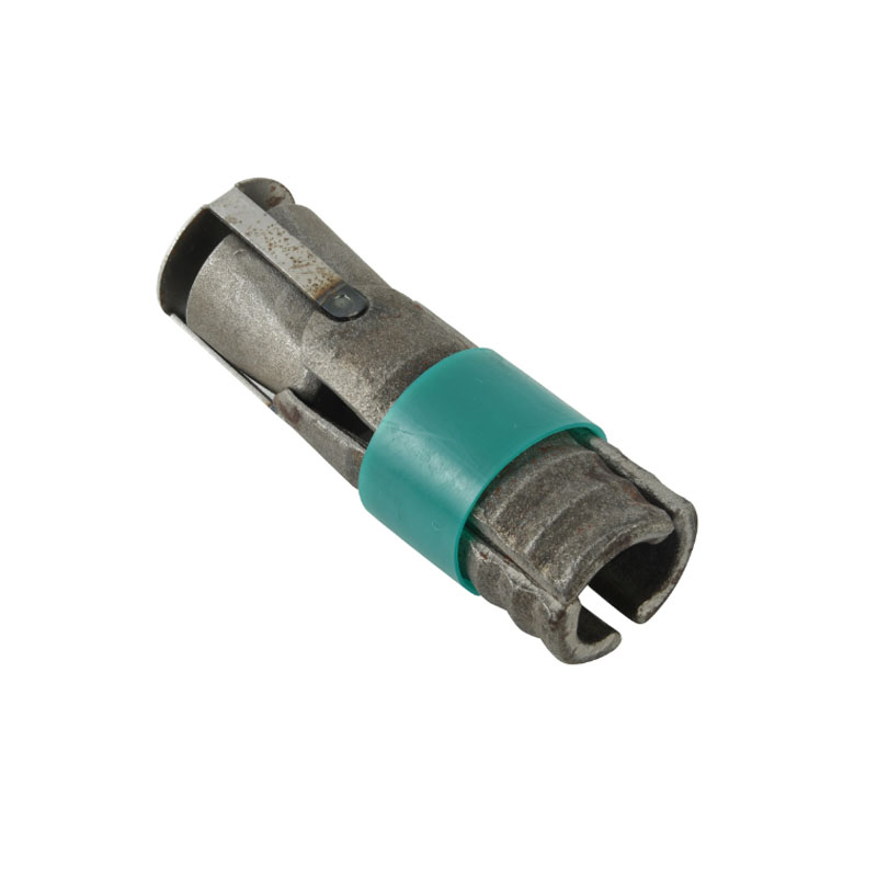
Custom Expansion Shell Bolt Options for Heavy-Duty Anchoring Applications
2026-11-02
When standard expansion shell bolts fall short in demanding heavy-duty anchoring jobs, the difference often comes down to tailored design. From unusual base materials to extreme load requirements, off-the-shelf hardware rarely covers every field condition. That’s where custom options from Supreme Machinery change the equation—giving engineers and contractors a way to match thread geometry, shell expansion range, and coating specs to the actual installation environment. In this post, we’ll break down the key customization choices that can keep your anchoring system reliable when it matters most.
Customizing Expansion Shell Geometry to Grip Irregular Boreholes
Standard expansion shells assume a near-perfect cylindrical borehole, but real-world drilling often leaves oval sections, ledges, or rough patches. When the shell petals make contact only at scattered high points, the load concentrates in small areas, reducing pull-out resistance and causing premature slip. Customizing the shell geometry starts with mapping the actual borehole profile—either through laser scanning or simple impression tools—then adjusting the petal curvature and hinge angles so that more surface area engages the uneven wall.
Beyond simple curvature changes, designers can vary the number of petals, their individual widths, and the tooth pattern along each edge. For highly irregular holes, a segmented shell with independently flexing leaves works better than a rigid cone, letting each leaf conform to local dips and bumps. Adding asymmetric serrations or stepped contact pads on the outer face also helps bite into soft or fractured rock without overstressing the shell body itself.
A well-tuned custom shell can raise anchoring capacity by 30–50% in bad ground compared to an off-the-shelf unit, but it demands careful torque control during installation. Over-expanding a conforming shell may cause individual petals to buckle inward, reducing contact. Field tests typically involve pulling the shell through a mock irregular borehole to refine the geometry before finalizing the design for production.
High-Strength Alloy and Coating Pairings for Corrosive Anchor Sites
Pairing a high-strength alloy with the right coating system starts with the anchor’s exposure profile. In splash zones and buried marine soils, duplex stainless grades like UNS S32205 or S32750 give roughly twice the yield strength of 316L while resisting chloride pitting and crevice corrosion. Where chlorides combine with sour gas or elevated temperatures, nickel-based alloys such as Alloy 625 become the safer substrate. Yet even these alloys can suffer localized attack at thread roots or under loose washers, so the coating must work with the alloy rather than simply covering it.
For subsea and tidal anchors, thermally sprayed aluminum over super duplex UNS S32750 remains a reliable combination. The aluminum layer acts as a galvanic anode, protecting exposed steel at scratches or coating holidays, while a thin sealer slows aluminum consumption in the first months. On high-strength low-alloy steel anchors (e.g., AISI 4340 tempered to below 22 HRC), a zinc-rich epoxy primer plus a polyurethane topcoat offers both barrier protection and sacrificial action. That pairing works only if the steel hardness is controlled and cathodic protection is limited, otherwise hydrogen uptake can trigger delayed fracture at high-tensile threads. For splash-zone attachments where maintenance is difficult, a duplex substrate with an epoxy intermediate coat and a UV-stable polyurethane finish will outlast plain carbon steel with the same coating stack.
Derating Factors That Change Pull-Out Capacity in Heavy-Duty Bolts
Pull-out capacity in heavy-duty bolts rarely matches the idealized values listed on datasheets. One of the most overlooked derating factors is thread engagement length relative to the base material hardness. When a bolt is threaded into a softer parent metal—such as cast aluminum or mild steel plate—the effective load distribution along the engaged threads becomes uneven, concentrating stress at the first few threads near the surface. Even a small reduction in engagement, from 1.5 times the bolt diameter down to 1.0 times, can drop pull-out resistance by 20 to 30 percent in these softer substrates. Engineers often compensate with thread inserts, but those introduce their own derating due to insert installation tolerance and the reduced cross-sectional area of the tapped hole.
Temperature swings add a second layer of derating that many static calculations miss. In applications where a heavy-duty bolt cycles between hot and cold, differential thermal expansion between the bolt and the clamped material can loosen the preload over time. This loss of clamp force directly lowers the pull-out threshold because the remaining tension is what resists axial extraction. For bolted joints on exhaust manifolds or engine blocks, a temperature differential of 150°C can reduce pull-out capacity by as much as 40 percent compared to room-temperature values, even if the bolt itself never yields.
Finally, installation variables such as tapping speed, cutting fluid residue, and thread-forming versus thread-cutting methods alter the micro-geometry of the internal threads. Rolled internal threads in ductile metals often show higher pull-out strength than cut threads because of work hardening, but if the hole is over-tapped by just a few hundredths of a millimeter, the gain disappears. Field measurements from torque audits show that inconsistent thread fit—ranging from class 2B to class 3B on the same assembly line—can introduce a derating factor of 1.2 to 1.5 on the expected pull-out load, making it a silent but critical variable in heavy-duty fastener design.
Thread and Shoulder Modifications That Prevent Eccentric Loading
When a fastener tightens against a surface that isn’t perfectly square, the load path shifts away from the central axis. A common fix is to alter the thread runout near the head. By adding a slight undercut or relief groove just below the head, the last engaged thread no longer acts as a hard stop that forces the shank to bend. Instead, the fastener can settle into the mating threads with less side force, keeping the tension line closer to the centre.
Shoulder geometry plays a similar role. A short cylindrical shoulder with a carefully controlled radius at the transition to the threaded section reduces stress concentration and allows slight angular adjustment before full clamp load is reached. In some designs, a convex or spherical shoulder face is used to mimic a ball-and-socket contact, which prevents a rigid edge from digging in on one side. That edge contact is often the hidden source of eccentric loading in supposedly rigid joints.
Thread flank modifications can also help. For example, a slightly reduced major diameter on the first few threads near the shoulder makes the engagement more gradual. The local reduction lets the bolt or screw centre itself in the tapped hole before the fully formed threads take over. Combined with a generous under-head radius, this approach spreads the seating forces evenly and avoids the bending moment that leads to early fatigue or loosening.
Multi-Stage Shell Expansion for Sustained Vibratory Loads
Multi-stage shell expansion offers a practical route for managing sustained vibratory loads without resorting to overly stiff or bulky designs. Instead of a single, abrupt expansion that concentrates stress at one cross-sectional transition, the shell opens in a series of stepped increments. Each increment allows local deformation to redistribute before the next expansion, effectively lowering peak strain amplitudes along the shell body.
Under continuous vibration, this incremental geometry acts like a mechanical filter. High-frequency energy that would otherwise reflect at a sharp discontinuity is partially absorbed and scattered across the multiple interfaces. The result is a more even fatigue-life profile, especially near welded or riveted joints where abrupt section changes tend to initiate cracks. Engineers can tune the number and spacing of expansion stages to shift resonant modes away from operating frequencies.
In practice, the trade-off is added fabrication complexity versus improved endurance. However, for components such as exhaust bellows, pressure vessel skirts, or rotor casings that see long-duration oscillating loads, multi-stage expansion often pays for itself by extending service intervals and reducing field failures tied to vibration-induced fatigue.
Matching Nonstandard Bolt Lengths to Deep Embedment Requirements
When embedment depth requirements exceed what a standard bolt length can provide, nonstandard lengths become necessary. A 5/8-inch diameter anchor specified for 6-1/2 inches of embedment might only be available off the shelf in 6- or 8-inch lengths. Using the 6-inch bolt results in inadequate embedment, while the 8-inch bolt may project too far above the baseplate or interfere with adjacent hardware. In these cases, ordering bolts in 7-inch or 7-1/2-inch lengths allows the anchor to reach the full required depth without excessive protrusion.
Nonstandard lengths should be specified based on the distance from the underside of the head to the tip, not the overall length including the head. For deep embedment in concrete or grouted applications, add the thickness of the baseplate, any levelling nuts or washers, and the required thread projection for the nut. A common oversight is failing to account for the taper at the end of a rolled-thread bolt or the reduction in thread length when a bolt is cut from all-thread rod. If the anchor must develop tension deep within the substrate, verify that the reduced-diameter section or the cut end does not compromise pullout capacity.
Sourcing nonstandard lengths often involves longer lead times and minimum order quantities, so it pays to check whether a standard length can be trimmed or whether a threaded rod with a coupler can serve the same purpose. However, field cutting a standard bolt usually removes the protective coating and may leave a rough end that damages internal threads in an anchor nut. For critical deep embedment applications, a factory-produced nonstandard bolt with proper thread rolling and coating is usually the safer choice, even if it requires planning ahead.
FAQ
We can supply carbon steel, alloy steel, and various stainless grades such as 304 and 316. For highly corrosive or high-temperature environments, custom alloys like duplex or 17-4 PH are possible, with heat treatment tailored to the required strength and ductility.
Yes, thread length, overall length, and diameter can all be specified beyond standard ranges. This allows the expansion shell to sit at the correct depth in cracked or uncracked concrete while keeping the fixture nut accessible.
Hot-dip galvanizing, zinc-nickel, and Xylan or PTFE coatings are common choices. For marine or industrial chemical settings, a multi-layer system combining sacrificial plating with an organic topcoat often outperforms a single heavy coating.
Hex heads remain the default for wrench tightening, but heavy hex, flanged hex, or square heads can be furnished. A flanged head distributes bearing stress over a wider area, which is useful when anchoring into softer base plates or oversized holes.
Rather than relying only on catalog values, specify the required tensile and shear capacities, concrete compressive strength, and whether the anchor will be in cracked or uncracked concrete. The expansion shell design, bolt grade, and embedment are then sized together to meet those loads.
Yes, custom outside diameters of the expansion shell and tapered plug can be machined to fit oversized or worn holes. This helps restore pull-out resistance without re-drilling or using chemical adhesives.
For dynamic loads, we recommend a combination of ductile bolt material, deeper embedment, and a shell with serrated or undercut features. Some projects also add a lock washer or wedge-locking nut to prevent loosening under continuous vibration.
Conclusion
When standard expansion anchors fail in heavy-duty applications, the real difference often lies in how the shell is shaped to the borehole. Irregular drilling in fractured rock or worn concrete demands customizable shell geometries that can conform to uneven walls. Instead of relying on a uniform split, manufacturers can machine tapered leaves or serrated contact edges to increase grip where the hole is oversized or out-of-round. At the same time, selecting the bolt alloy and protective coating must match the installation environment. High-strength steels paired with hot-dip galvanizing or ceramic-filled coatings provide better resistance in corrosive anchor sites, but the combination also influences thread fatigue and long-term relaxation.
Beyond material selection, pull-out capacity is rarely the catalog value once site conditions come into play. Derating factors such as edge distance, hole cleaning, and moisture can cut ultimate load well below laboratory figures. To preserve capacity, thread and shoulder modifications are used to keep the bolt concentric under load, preventing eccentric stress that peels one side of the shell. For sustained vibratory loads, multi-stage shell expansion offers sequential setting where inner and outer leaves engage separately, maintaining preload as the substrate shifts. Deep embedment requirements may demand nonstandard bolt lengths, and a matched thread run with an extended expansion cone ensures the anchor develops full resistance without bottoming out or leaving weak threads in the shear plane.
Contact Us
Contact Person: Paul
Email: [email protected]
Tel/WhatsApp: 8615067447509
Website: https://www.spironcasting.com