
Chip Resistor Recommended List for Reliable Electronics Design
2026-08-19
Ask any hardware engineer what keeps them up at night and chip resistor selection rarely tops the list—until a field return traces back to a part that drifted under load or cracked during thermal cycling. A practical recommended list changes that. Drawing on real-world failure analysis and production insights from Milliohm, this guide lays out the chip resistor types, tolerance bands, and package choices that consistently survive prototyping and volume builds. Whether you are tightening a precision sense circuit or hardening a power stage, the shortlist ahead helps you skip the guesswork and avoid the silent failures that only show up after deployment.
Critical Parameters for Selecting Reliable Chip Resistors
When narrowing down chip resistor options, the first place to look is often the datasheet's trio of tolerance, temperature coefficient of resistance (TCR), and power rating. These specs define how far the actual resistance can drift from nominal at room temperature, how much that value shifts as the board heats up or cools down, and how much dissipated heat the part can safely handle. But experienced engineers know that these headline numbers only tell part of the story. For example, a 1% tolerance with a ±100 ppm/°C TCR may be fine for a pull-up resistor, but completely inadequate for a precision analog front end or feedback network where a few milliohms of drift can corrupt a measurement.
Beyond the basics, reliable chip resistor selection hinges on parameters that are easy to overlook: voltage coefficient, current noise, short-time overload capability, and long-term stability under high humidity or thermal cycling. A resistor rated for 250 mW at 70°C might derate steeply above that temperature, so always check the power derating curve and consider the actual hot-spot temperature on your board. Sulfur-resistant chip resistors are also worth considering in industrial or automotive environments where airborne sulfur compounds accelerate silver sulfide growth and cause open circuits. Finally, if the application involves pulse loads or frequent inrush currents, look for a pulse-withstanding specification rather than relying solely on average power ratings.
One practical way to differentiate a reliable chip resistor from a merely adequate one is to examine qualification data. AEC-Q200 compliance, moisture sensitivity level, and solder heat resistance all point to a robust construction and stable thick or thin film element. In critical circuits, choose a larger case size than the minimum required to improve heat dissipation and mechanical stress resistance, and consider specifying tighter drift limits over time and temperature rather than just initial tolerance. These small details often separate a design that works for a year in the lab from one that lasts a decade in the field.
How Surface Finish and Termination Affect Long-Term Stability
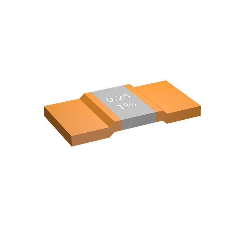
Surface finish does far more than protect copper from immediate oxidation. The microstructure and roughness of the final plating directly shape how a conductor ages. At frequencies where current crowds into the outer few micrometres, even slight increases in surface roughness raise effective resistance and insertion loss. Over time, finishes with poor barrier properties allow copper to migrate into the gold or silver layer, forming intermetallic compounds that are brittle and electrically lossy. Immersion silver, for example, can tarnish in sulphur-rich environments, while thick gold over nickel remains conductive but may build up nickel oxide at exposed edges. Each finish has a distinct failure timeline, and that timeline is rarely linear.
Termination metallurgy adds a second layer of risk. The point where a component lead meets the board finish is a junction of three or more different metals, each with its own diffusion rate and galvanic potential. Solder joints that look pristine after reflow can degrade through the slow growth of Cu6Sn5 and Cu3Sn intermetallics at the interface. If the nickel barrier under a gold finish is too thin or porous, copper from the underlying trace can reach the surface and oxidise, raising contact resistance. Tin-lead versus lead-free solders also age differently; lead-free joints tend to form thicker intermetallic layers and are more prone to tin whisker growth under compressive stress. The long-term stability of the termination depends not only on the materials chosen but on the plating thickness, grain size, and the amount of thermal cycling the assembly sees.
Perhaps the most overlooked factor is how finish and termination interact under combined stressors. A board with excellent corrosion resistance but a mismatched solder alloy can fail earlier than a cheaper finish with a well-chosen termination. Damp heat testing can expose galvanic corrosion between silver and nickel, while thermal shock tends to crack intermetallic regions that have become overly thick. Mixed flowing gas tests reveal sulphide attack on silver and porous gold. Designers often optimise for reflow yield and initial electrical performance, but long-term stability is dictated by these slower chemical and metallurgical processes. Choosing a finish without understanding the termination's barrier layer is a gamble that may not show up for years.
Power Derating Strategies for High-Temperature Environments
Running electronics near their thermal ceiling is less about finding one magic number and more about mapping how much margin actually remains as ambient temperature climbs. A common starting point is the manufacturer’s safe operating area curve, but practical derating often needs to begin earlier than the datasheet suggests—especially when enclosures trap heat or airflow is uneven. Instead of applying a flat 20% cut across the board, it helps to identify the few components that reach high junction temperatures first and pull their dissipation down selectively, leaving cooler parts untouched.
Board-level decisions can shift the derating threshold significantly. Thicker copper pours, thermal vias under hot packages, and wider trace necks reduce the temperature rise per watt, which means less aggressive derating is needed for the same reliability target. At the same time, losses that scale with switching frequency or gate drive voltage deserve attention: lowering a converter’s switching frequency by 10–15% in a hot environment can reduce dynamic losses enough to avoid a larger cut in output current. Passive airflow improvements, such as orienting fins vertically or creating a low-resistance exit path, often deliver more benefit than simply increasing heatsink mass.
On the control side, derating should include more than just the power stage. Firmware can monitor internal temperature sensors and back off load current, fan speed, or charge rate in steps before hitting hard limits. In multi-rail systems, shifting load from a heavily derated rail to one with more thermal headroom keeps overall throughput higher. The goal is to treat derating as a dynamic response rather than a fixed label, so the system holds its performance in normal conditions and only sacrifices output as the environment genuinely approaches the danger zone.
Why Thin Film Resistors Excel in Precision Analog Circuits
Precision analog circuits live and die by the stability of every passive component in the signal path. Thin film resistors earn their place because of an unusually tight combination of low temperature coefficient of resistance (TCR) and minimal voltage coefficient. A 25 ppm/°C TCR might sound marginal, but over a 20°C ambient swing, a standard thick film part could drift enough to swamp a 16-bit converter's least significant bit. Thin film's sputtered nichrome or tantalum nitride layer, typically only tens of nanometers thick, responds to thermal stress with far less resistance change, keeping gain and offset errors predictable.
What really separates thin film from competing technologies is the way the resistive element is trimmed. Laser trimming cuts a precise serpentine or ladder pattern into the film, adjusting the value to within 0.01% if needed. More importantly, the trim geometry reduces hot spots and current crowding, which lowers both 1/f noise and long-term drift. In a precision instrumentation amplifier or a reference divider, this translates to cleaner baselines and less recalibration over the product's life.
Designers also lean on thin film for its excellent matching and tracking between adjacent resistors on the same substrate. Because all elements see the same deposition and annealing, ratio stability can reach 0.1 ppm/°C over a moderate range. That makes thin film networks the default choice for differential amplifiers, R-2R ladders, and bridge circuits where common-mode rejection depends on resistor ratios staying locked together. The slight cost premium over thick film is trivial compared to the performance penalty of losing one bit of resolution or adding an extra calibration step.
Matching Chip Resistor Footprints to Thermal and Mechanical Stress
When a chip resistor footprint is oversized relative to the actual component body, the solder fillet becomes the primary load-bearing element during thermal cycling. That extra solder volume does not simply add compliance; it concentrates strain at the heel and toe fillets, where cracks typically initiate. A tighter footprint with reduced pad extension forces the solder joint into a barrel-shaped geometry, lowering the average strain per thermal excursion and extending cyclic life. This is especially relevant for resistors rated above 100 milliwatts, where self-heating adds a second thermal gradient on top of ambient fluctuations.
Mechanical stress from board flexure tends to localize at the resistor's termination edges, not across the entire pad. If the footprint designer leaves generous copper on the non-soldered side of the termination, the joint stiffness increases and stress transfers into the ceramic body, raising the risk of microcracks under repeated bending. A balanced approach is to shave the inner pad edges closer to the component center while keeping the outer edges slightly longer for inspection access. This asymmetry allows the solder to absorb bending energy without over-constraining the brittle alumina substrate.
For high-reliability designs, the pad width relative to the termination width also dictates how well the resistor dissipates heat into the board. Narrow pads act as thermal bottlenecks, causing the termination temperature to rise and increasing the mismatch between the resistor's coefficient of thermal expansion and the FR-4. A practical rule is to make the pad width at least 90% of the termination width but no more than 110%—wider pads pull heat away efficiently but add unnecessary solder volume that stiffens the joint against in-plane expansion. This window keeps both thermal and mechanical strains within the fatigue limit for common tin-lead and lead-free solders.
Validation Testing Methods for Harsh Environment Resistors
Validation testing for harsh environment resistors goes beyond confirming tolerance at room temperature. A resistor that looks stable on a benchtop can fail quickly when faced with thermal shock, condensing humidity, or trace sulfur compounds. Modern validation protocols therefore combine several stress conditions in sequence, not just as isolated checks. This matters because real deployments rarely expose components to one stress at a time; a circuit in an outdoor enclosure may see temperature swings while moisture condenses on the board, and a resistor near an engine harness may face both vibration and chemical fumes.
Common electrical and environmental tests include thermal cycling from -65°C to +175°C for several hundred cycles, damp heat with bias at 85°C/85% RH, and exposure to hydrogen sulfide or sulfur dioxide gas to check for silver or nickel-chromium film corrosion. Resistors intended for downhole tools or aerospace modules may also undergo salt spray, immersion in oil or drilling fluid, and high-pressure autoclave testing. During these exposures, change in resistance is logged continuously and after each block; a typical acceptance limit might be ±0.5% shift with no mechanical cracking or insulation breakdown.
Mechanical validation covers shock pulses, random vibration profiles, and board flex, often repeated after thermal aging to catch solder joint fatigue. Power overload and pulse handling tests are used to confirm the element can survive short transients without drifting permanently. The most useful validation plans include destructive physical analysis on a small sample after stress, looking for delamination, terminal corrosion, or resistive film thinning. Passing a single environmental test says little; the evidence becomes convincing only when multiple stress types are stacked and the resistor still holds its specified tolerance.
FAQ
A focused list cuts design time and reduces procurement mistakes. It limits the universe to parts with proven field history, stable availability, and consistent derating behavior, so you don't gamble on an unknown commodity resistor in a critical signal path.
Common choices include Panasonic ERJ, Yageo RC, Vishay CRCW, Bourns CR, KOA Speer RK73, and Susumu RG. These families span thick film, thin film, and current-sensing roles, and they have long product lifecycles that align with industrial and automotive design timelines.
Beyond resistance and tolerance, focus on temperature coefficient, power rating at your expected operating temperature, voltage handling, pulse withstand capability, and moisture sensitivity. A resistor that looks fine at room temperature can fail quickly under combined thermal and voltage stress.
Thick film parts are cost-effective and robust for general use, but they can be noisier and have looser TCR. Thin film resistors offer tighter tolerance, lower noise, and better long-term stability, making them preferable for precision analog, feedback networks, and reference circuits.
Derating is what turns a good part into a reliable one. Many designs limit continuous power to 50–70% of the rated value at elevated ambient temperatures. Without proper derating, solder joint fatigue and resistance drift become far more likely over a product's life.
0402 and 0603 are standard workhorses, but 0805 and 1206 offer better power dissipation and mechanical robustness for higher stress nodes. Very small sizes like 0201 can be problematic in harsh environments due to lower heat capacity and greater sensitivity to board flex.
Current sense resistors demand attention to TCR, thermal EMF, and Kelvin connection layout. Look for dedicated low-ohm series with metal alloy elements or thick film tuned for low resistance. Their stability under repeated thermal cycling matters more than their initial tolerance.
Avoid choosing based on lowest price, ignoring pulse derating, neglecting PCB pad design, or mixing incompatible termination materials with high-reliability solder joints. Also don't assume a single resistor family suits every role; analog front ends and power paths need different characteristics from the same list.
Conclusion
A dependable chip resistor selection guide for rugged electronics demands more than a standard datasheet scan. Start by prioritizing critical parameters: tolerance stability over temperature, voltage coefficient, and noise performance, especially when thin film types are considered for precision analog front-ends. Surface finish and termination material choices, such as tin-lead versus matte tin or epoxy-based edge terminations, directly influence solder joint integrity and long-term drift under thermal cycling. In high-temperature environments, derating curves must account for hot spots on the PCB, not just ambient air, so reduce nominal power by at least 50% above 85°C and verify pulse handling. Thin film resistors shine in feedback networks and reference dividers because their low current noise and tight TCR tracking keep offset errors small, but they require careful footprint design to avoid mechanical stress from board flexure or thermal expansion mismatches. Matching pad dimensions and using stress-relief cutouts near heavy components prevents microcracks that degrade resistance values silently over years.
For harsh environment validation, go beyond standard 1000-hour life tests: include powered thermal shock, biased humidity with condensation cycling, and sulfur exposure for industrial or automotive edge cases. A recommended list should group resistors by construction—thick film for general pulse robustness, thin film for precision, metal foil for ultra-stable references, and wide-terminal or anti-sulfuration types for high-reliability power rails. Avoid blindly trusting vendor “high reliability” labels; instead, request per-lot data on solder heat resistance, board flex performance, and endurance under rapid temperature change. By combining derating strategy, termination analysis, footprint mechanical matching, and targeted validation, engineers can narrow down a shortlist that survives repeated power cycles, vibration, and moisture ingress without parametric shift. This practical approach turns a generic selection guide into a field-proven roadmap for reliable electronics design.
Contact Us
Contact Person: Yuying Gao
Email: [email protected]
Tel/WhatsApp: +86 18926013721
Website: https://en.milliohm.net/